All versions of ARTeMIS Modal support classical modal analysis also known as Experimental Modal Analysis(1).
FRF’s can be uploaded using Universal File Format (UFF/UNV), or be internal estimated by uploading input and output time domain measurements in the Manage Measurement Task, or by using the Impact Testing Module2.
Multiple Input Multiple Output Modal Technology
All methods for Experimental Modal Analysis in ARTeMIS Modal are born multiple input multiple output polyreference methods. This means that the techniques are capable of estimating closely space modes and even repeated modes with a high degree of accuracy. Below there is an example of a perfectly symmetric structure where the polyreference methods have been applied on a setup with two reference accelerometers and a rowing impact hammer.
All-in-one Solution for Selected Data Acquisition Hardware
ARTeMIS Modal supports direct control of selected data acquisition hardware. If a data acquisition plugin is available along with the EMA plugin, then it is possible to perform a complete impact testing using ARTeMIS Modal. Below it is also shown how the above example has been created using impact testing.
Easy Import of Frequency Response Functions from Third Party Providers
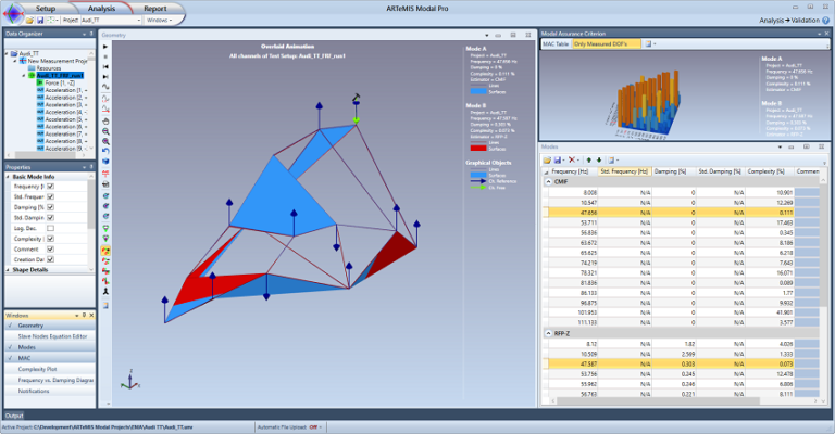
ARTeMIS Modal is designed to work with geometry information and Frequency Response Functions obtained from third party providers. Through the Universal File Format standard all can be uploaded from a single or multiple files. See the example below showing how a modal test of an Audi TT is imported from a third party provider in this way.
Two polyreference methods are available; CMIF Peak Picking and RFP-Z polynomial estimation.
Benefits
Intuitive modal parameter estimation based on peak-picking in frequency domain.
Immediate results even in case of hundreds of measurement points and modes.
Extremely robust being based on the Singular Value Decomposition of the matrices of the Frequency Response Functions.
Handles single- or multiple test setups and single- or polyreference in exact same way.
Benefits
Estimates global modes from stabilization diagram of modes extracted from rational polynomials.
Estimates natural frequencies, damping ratios and mode shapes using Automatic Mode Estimation.
Cursors used to select the frequency range to use in the polynomial estimation.
Optional correction of damping estimates in case exponential windows are used during internal impact testing.(2)
Handles single- or multiple test setups and single- or polyreference in exact same way.
Experimental Modal Analysis using ARTeMIS Modal
December 2023
1: Requires the Experimental Modal Analysis plugin.
2: Requires the Experimental Modal Analysis and a data acquisition plugin.
Below two Experimental Modal Analysis examples are shown. The first demonstrate the use of the internal impact testing module. The second demonstrate how to upload and analyze FRF’s obtained from third party software.
This example demonstrate the impact testing module as well as the two polyreference methods for EMA in ARTeMIS Modal. The structure is a symmetric steel plate with dimensions 300 x 300 x 8 mm. Two accelerometers has been mounted as references and the impacts were made in 16 positions in a 4 x 4 grid.
The test and analysis can be seen in the three YouTube videos below:
Part 1. Setting up an ARTeMIS Modal project for EMA
Part 2. Performing the actual impact testing
Part 3. CMIF Peak Picking and RFP-Z modal analysis
Below the final results are depicted.
Complex Mode Indicator Function – Peak Picking
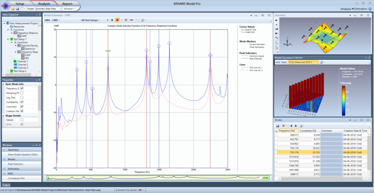
When having multiple references there will be multiple singular value lines in the Complex Mode Indicator Function. In the case of a symmetric structure there will be multiple modes having more or less the same natural frequency. In this case the different modes are picked at the different singular values. This is necessary for three frequency location in the present example.
Rational Fraction Polynomial in Z domain (RFP-Z)
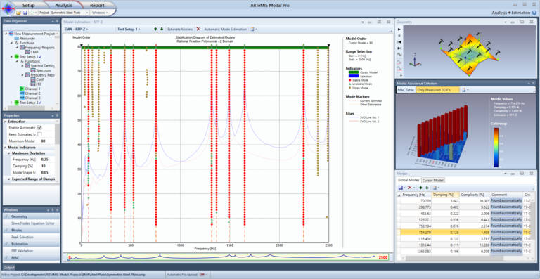
This method estimates the global modes by creating a stabilization diagram from which stable (physical) modes are picked out automatically. The primary user inputs are to specify the maximum model order, the frequency range of interest, and possibly modify the modal indicators to help the automatic search for global modes.
The experimental tests presented here has been conducted at TH Ingolstadt, Faculty of Mechanical Engineering, Germany under the guidance of Professor J. Bienert, who is gratefully acknowledged.
The experimental campaign consists of impact (hammer) testing of an Audi TT car body, see a picture depicted below.
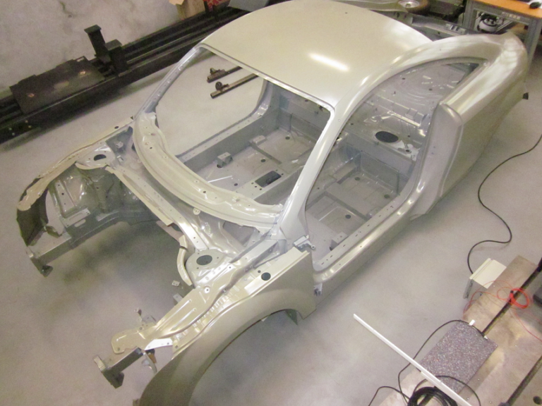
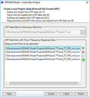
The car body was mounted free on four air cushions. Four references respectively impact points were excited with 14 accelerometers as responses. The data acquisition and processing of the FRF’s were made with a 24-channel data acquisition system. The FRF’s were stored in the four separate Universal File Format Files (Audi_TT_FRF_runX.unv) along with a test geometry in its own file (Audi_TT.unv).
Importing FRF’s into ARTeMIS Modal
Importing the FRF’s into ARTeMIS Modal starts with creating a new project using Universal File Format, which is illustrated in the picture below.
Once the files are uploaded, the geometry and FRF’s can be seen in the simplified Prepare Data task. The Data Organizer contains all four impact tests listed below each other, and the Geometry window visualize the positions and the directions of the response and reference channels. All the impact positions can be viewed by selecting the first item, All Test Setup, in the Data Organizer, illustrated below.
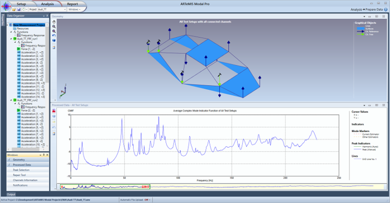
The 14 response accelerometers are seen in blue, and the impact positions, indicated by a hammer symbol, are colored green.
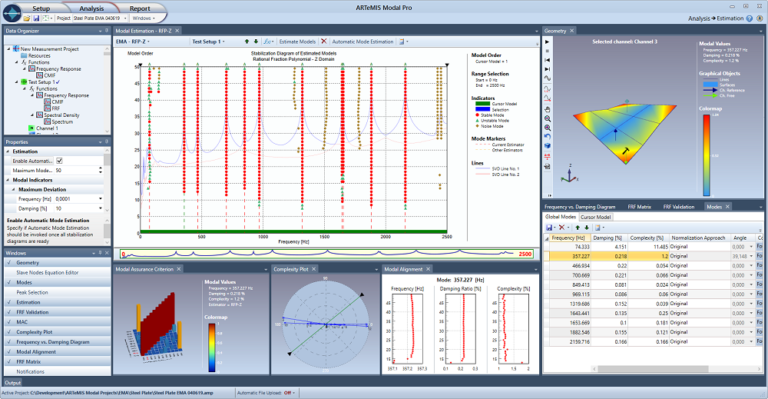
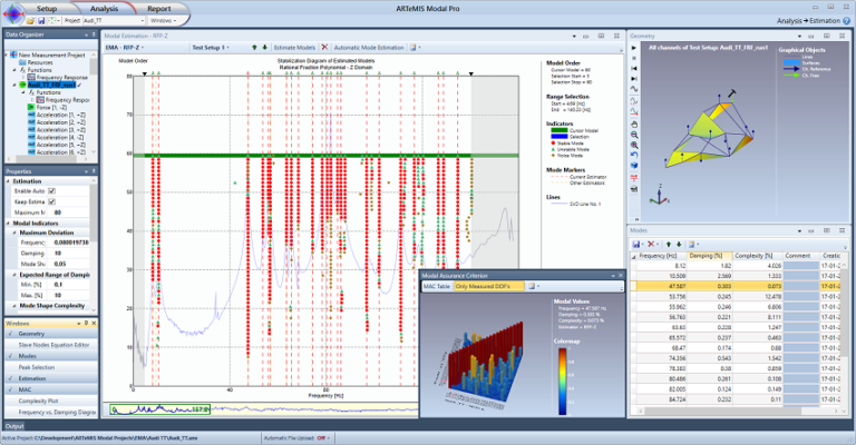
The modal parameters of the car body are computed with the RFP-Z method. The work flow is as follows:
Select a maximum model order to initialize the estimation of the system matrices of the highest dimension for the subsequent computation of a lower model orders.
Select the desired frequency band.
Select a specific range of the model orders by dragging the mouse down on the stabilization diagram, or simply click the Estimate Models button to estimate all the model orders.
Stable modes are found by a study of the natural frequencies, damping ratios and mode shapes (MAC and maximum modal complexity).
Global modes are estimated based on the stable modes in the diagram.
The figure below illustrates the analysis of the experimental test of the Audi TT in the frequency range from around 4 Hz up to 140 Hz. Maximum model order was set to 80, however only models up to 60 were estimated.
The modes obtained from the RFP-Z estimator are validated using the standard tools available in ARTeMIS Modal. By selecting the Validation Task, the modes can be compared with the other estimators as well as imported results from any other modal analysis tools. Below we are comparing the RFP-Z modes with the modes obtained with a simple peak-picking tool already available in ARTeMIS Modal. It is based on the peak picking on the Complex Mode Indicator Function (CMIF).
