The example that is described in this tutorial is also located in the folder Examples\Geometry Building Model\ and called Geometry Building Model.amp.
In this step we will produce a square plate as a basic object for later use.
Insert new Geometry Object
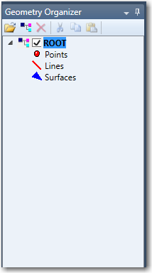
The first step is to insert a new empty object. The plate could be drawn inside the ROOT object, but since we later want to copy it has to be separate object. The way to insert a new object is to activate the context sensitive menu of the Geometry Organizer and select the Insert button as shown below:
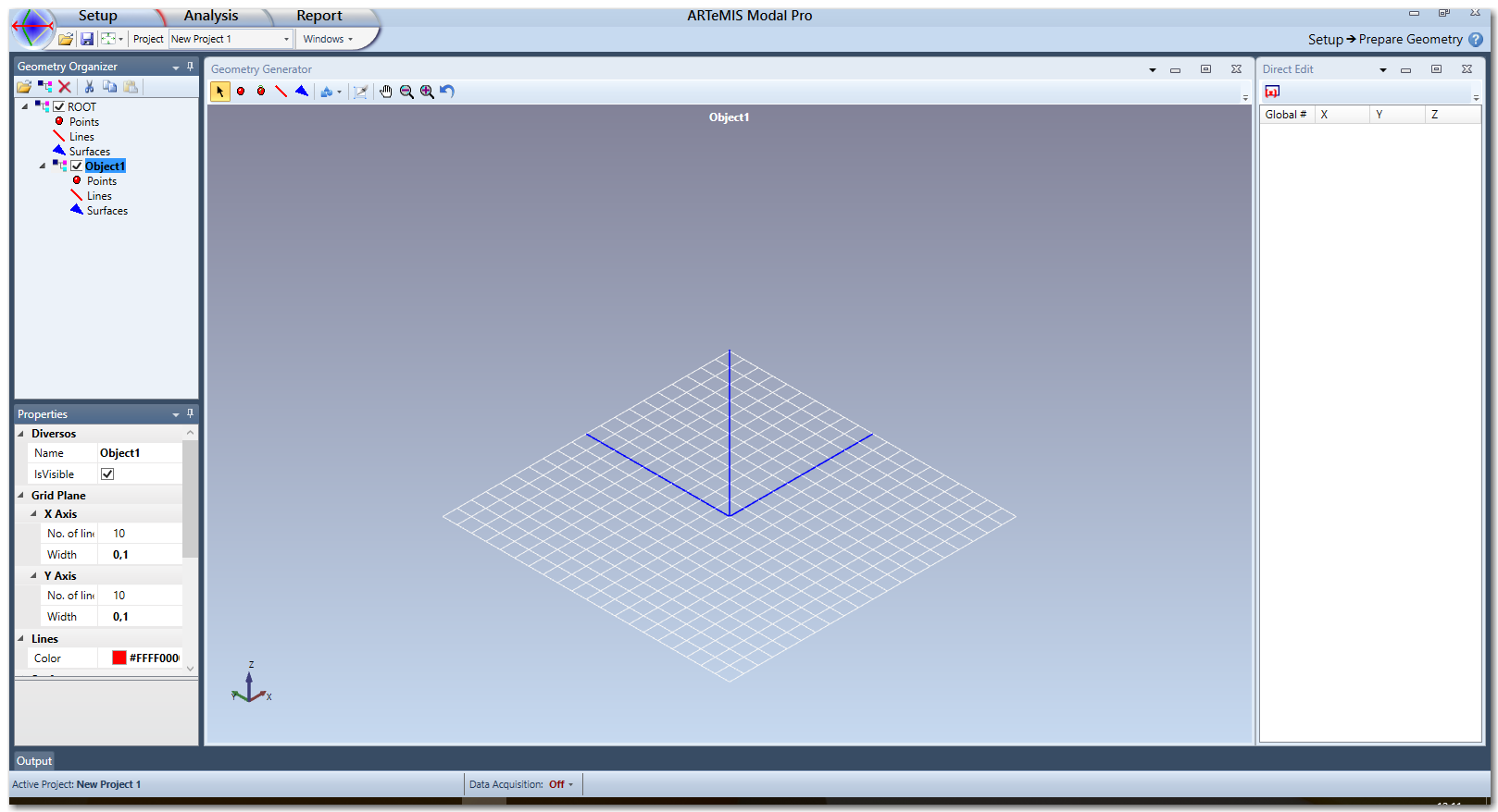
A new geometry object will now appear in the Geometry Organizer and its grid plane is shown in the Geometry Generator, see below:
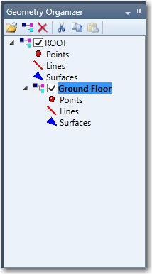
From the Properties Window the Name of the object can be renamed to object to Ground Floor.
Drawing points
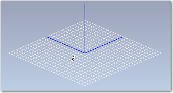
Now we will draw four points on the Plate objects grid plane. We start by activating the Add Points command by clicking the ![]() button in the toolbar in the top of the Geometry Generator Window. We then get a point drawing cursor and a red point that snaps to the grid plane as shown below
button in the toolbar in the top of the Geometry Generator Window. We then get a point drawing cursor and a red point that snaps to the grid plane as shown below
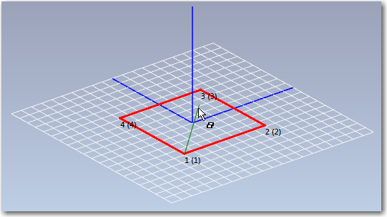
We can now position four points on the grid plane by clicking the left mouse button when the red point is in position. Below all four points are shown:
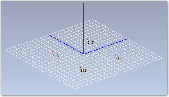
The numbers x(y) that appear next to the point needs a little explanation. x is the local number inside the object whereas (y) is the global and unique number. It is the number used for DOF assignment in the Assign DOF Information Task.
Drawing Lines
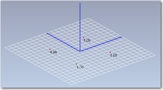
Now we will draw four lines between the points. We start by activating the Add Lines command by clicking the ![]() button in the toolbar of the Geometry Generator. We then get a line drawing cursor and the red points turn green when the cursor snaps to it as shown below:
button in the toolbar of the Geometry Generator. We then get a line drawing cursor and the red points turn green when the cursor snaps to it as shown below:
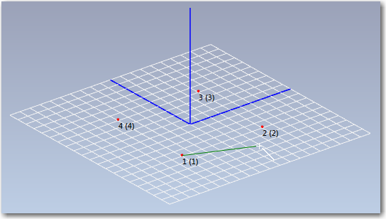
By clicking the left mouse button the line drawing is started and the line is locked to the point and can be dragged to the next point as shown below:
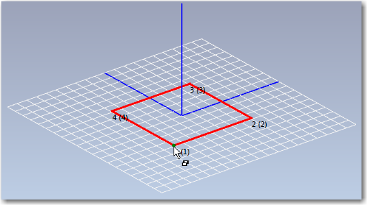
The ending point of the line is then snapped and the left mouse button pressed which completes the drawing of this line. We can then continue with the three remaining lines as shown below:

Drawing Surfaces
Now we will draw two surfaces between the points. We start by activating the Add Surfaces command by clicking the ![]() button in the toolbar of the Geometry Generator. We then get a surface drawing cursor and the red points turn green when the cursor snaps to it as shown below:
button in the toolbar of the Geometry Generator. We then get a surface drawing cursor and the red points turn green when the cursor snaps to it as shown below:
The surfaces are constructed as triangles which means that we have to pick three points. The left mouse button is clicked on the first point as shown below:
Then the next point should be selected in clock-wise direction as shown below:
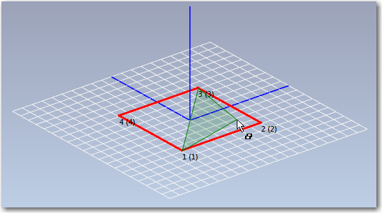
Finally, the last point is selected in clock-wise direction and the surface appear as shown below:
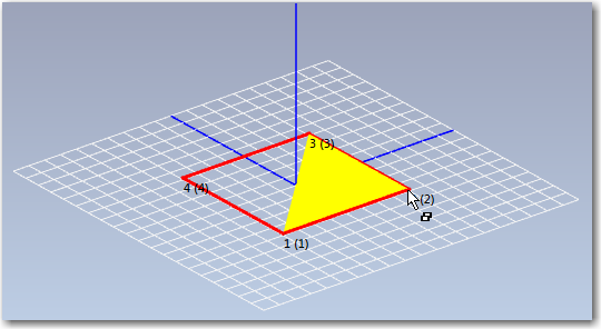
We then repeat the procedure to draw the last surface as shown below:
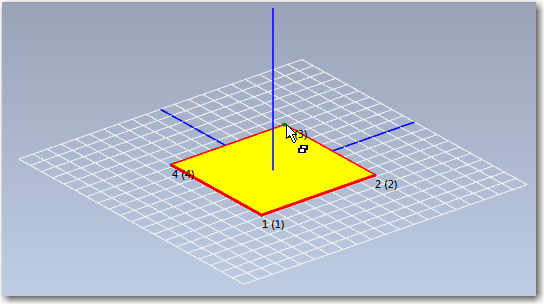
The reason for drawing in the clock-wise direction is that the surfaces have a front and a back with different colors. The reason is that if the geometry later only will be used for e.g. Finite Element Modeling, then it is important that the normal vector of the different surfaces are pointing in the same direction for plate structure like in this example.