
Setup 1 (Test setup 1)
Setup 2 (Test setup 2)
The group that starts with the Setups keyword is where the measured data is specified and linked to the geometry described be the lines and nodes. So this group define both where to load the data from and the DOF information. The required definitions for specification of one test setup (FrontEnd Object) are shown below, where < > specify a record field:
Setups
<Data set Label>
<Data File Name>
<DOF Node 1> <X> <Y> <Z> [<dB Ref> <Unit> <Type> <Label>]
In the first record you can enter a string with a short description of the test setup. In the second record you must specify the name, and optionally include the path, of the file that contains the measurements of this test setup.
Record three is the DOF definition record. The fields of this record are:
The node number where the transducer is mounted as integer.
The X-component of the directional vector that describes the direction of the transducer. This value can be any floating-point.
The Y-component of the directional vector that describes the direction of the transducer. This value can be any floating-point.
The Z-component of the directional vector that describes the direction of the transducer. This value can be any floating-point.
Reference value used to normalize e.g. spectral densities with when presented in dB displays. This value can be any positive floating-point.
String describing the unit of the measurements, e.g. m, m/s or m/s².
String describing the type of measurement, e.g. Displacement, Velocity, Acceleration.
A label string that serves as an ID of this particular transducer, e.g. Transducer #1.
Field 1 is the location of the specified DOF, and fields 2 to 4 is the vector that define the direction in which the transducer is pointing.
Note: The directional vector defined by fields 2 to 4 should usually be defined as a unit vector. The estimated mode shapes will be divided into the X, Y and Z directions by multiplication of these directional components. Thus, if the directional vector has a length different from unity this will affect the mode shape value in the point accordingly.
The fields 5 to 8 can be omitted. However, omitting one field imply that all remaining field also must be omitted. In other words, if you leave out field 5 you must also leave out 6 to 8.
The DOF definition records are repeated for all degrees of freedom in the data set. These records must be defined in the same order as the measurements of the DOF's are stored in the data file. The default data file format is a standard ASCII format where the measurements of the DOF's are stored column-wise. So the first DOF definition record corresponds to the first column, the second DOF definition record corresponds to the second column and so on. If you want to use the SVS binary data file format you must specify /binary after the file name in the <Data File Name> record.
All the above records define one data set only. If you have multiple data sets all the above records are repeated with values describing the next data set.
Note: In the case of multiple data sets there must be at least one reference transducer that is located in the same node and in the same direction in all data sets. That means in all the data set definitions there must be at least one record in which the at least first four fields are the same.
The building model example consist of two data sets with two reference transducer, which are located in nodes 5 and 6. The definition of the data sets is shown below. To the right of the definition there are comments describing the record and which data set it belong to:
Setups
|
|
|
Setup 1 |
Data set label. (Test setup 1) |
mes31set.asc |
Name of the file containing the measured data. (Test setup 1) |
2 0 1 0 0.000001 m/s² Acceleration Transducer 1 |
1st. DOF definition record. (Test setup 1) |
5 0 1 0 0.000001 m/s² Acceleration Transducer 2 |
2nd. DOF definition record. (Test setup 1) |
11 -1 0 0 0.000001 m/s² Acceleration Transducer 3 |
3rd. DOF definition record. (Test setup 1) |
6 0 1 0 0.000001 m/s² Acceleration Transducer 4 |
4th. DOF definition record. (Test setup 1) |
Setup 2 |
Data set label. (Test setup 2) |
mes32set.asc |
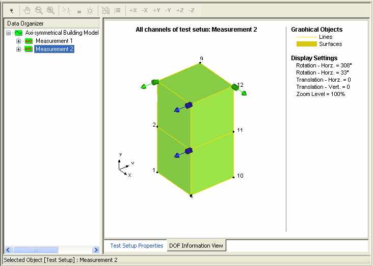
In the following the geometry as well as the location of the transducers of the two data sets are shown. The green arrows indicate the transducers relating only to the specific data set, whereas the blue arrows indicate the reference transducers. The direction of the arrows indicate the orientation of the directional vectors. If the length of one of these arrows is different from the others, it is an indication that the length of this directional vector is different from the others.
|
Setup 1 (Test setup 1) |
|
Setup 2 (Test setup 2) |